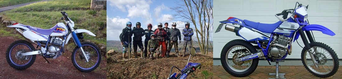
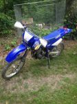
A forum for owners of Yamaha TTR250 trail and enduro bikes!

Members Login
Username 
 
Password 
    Remember Me  
Post Info TOPIC: CDi questions and answers!


Super Guru

Status: Offline
Posts: 8557
Date:
CDI questions and answers!
Permalink  


The following message is copied from the Yahoo Group forum on behalf of Brett:


"Sorry for not posting on the new forum, haven't joined yet. Maybe Brian can copy
my post over to the new forum if it gets any interest.

Was looking on eBay and saw a TTR250 CDI, fairly pricey, eBay item 280698833419

Says it's derestricted, wondering if anyone has bought one and what results they
had?"


__________________

Exeter, Devon, UK

http://www.ttr250.com  - The one and only dedicated TTR250 FAQ! 
 

TIP: For easy viewing bookmark the "Recent Posts" view - http://ttr250.activeboard.com/p/recent/ 

Lin


Senior Member

Status: Offline
Posts: 129
Date:
"Derestricted" CDi?
Permalink  


Have a look here: 

http://www.made-in-china.com/showroom/lixianda/product-detailKbgnwSFDMNWE/China-Digital-Electronic-CDI-Ignition-for-YAMAHA-Motorcycle-TTR250-4GY-.html

CDI made in China..?  Hmmmmm.......


__________________


Super Guru

Status: Offline
Posts: 2608
Date:
Permalink  
 

Does the Yamaha original limit horsepower?
Does the Yamaha original have rpm or speed limiters?
How can a CDI reduce oil consumption?
How does this CDI break "the analogue control of the traditional method"?

Seems very expensive at £154.49 and very vague on actual benefits, methinks someone's been peeking through rose-tinted spectacles

Martyn


__________________

You're never too old to learn something stupid

East Budleigh. Devon


Veteran Member

Status: Offline
Posts: 71
Date:
Permalink  
 

I'm with Martyn on this.

It looks like it can't offer much. How can it? Anyone ever wanted their TTR to rev higher?
No horsepower limit? When would a CDI do that? Maybe their confusing it with an ECU on an injected system.
'This series of digital ignition coil.....' OK, they really don't know what they're talking about.
'has the same shell and plug as the original car.' Great, but not really confidence inspiring.


Andy

__________________
Lin


Senior Member

Status: Offline
Posts: 129
Date:
Permalink  
 

 ...methinks someone's been peeking through rose-tinted spectacles cynic.gif....

Strikes me one could be peeking through a hole in the piston crown...

If the original CDI had a poorly developed advance map one could see room for improvement.  I would need a lot of convincing Yamaha's CDI was poorly developed.


__________________


Senior Member

Status: Offline
Posts: 208
Date:
CDi wires and terminals - removal
Permalink  


Hi guys.

I am putting the TTR back together and noticed that the wires coming out from the CDi and  just after the little rubber grommet in the cover are suffering from the outer sheath  being broken on some of the wires, and my question is: has anyone successfully removed the electrical connector block from the wires so as to be able to slide some heat shrink down the wire to the damaged area and if so how would i go about removing the connector, can it be done or is there a special gadget for the job.

Any info would be of a great help.

I don't want to put tape around the wires without putting some heat shrink on first. 

John.


__________________

1996 TTR 250 OE, 1996 YAMAHA WR 200, 1990 YAMAHA FZR 1000,2001 HONDA DEAUVILLE 650, 2005 TTR 250, 1998 Honda CR125R( in pieces) 1994 Kasawaski KX 250.


Super Guru

Status: Offline
Posts: 1156
Date:
RE: cdi wires
Permalink  


Yes....
get a VERY small flt blade screw diver... theres a tag on the steel conecter you have to bend in... it will pull out
reach in from the plug end .....Then rebend it back out before you reinsert the connecter blade back into the plastic block.....

A bit of peeing around but it can be done...

__________________


.....................................................................................................

 http://www.kiwibiker.co.nz

Bikes... 06 TTR250 / 09 XT660R / 1977 Montesa Cota 348 MRR / 1979 Montesa H6 125 Enduro...

E-mail  xtpete1@gmail.com


Super Guru

Status: Offline
Posts: 1324
Date:
Permalink  
 

You can also use a flat, pointy pair of scissors, just be careful not to slip with them.

Look down the side of the connector, one side will have a locking tab, you need to either push this in while pushing the connector out from the block, or just bend the locking tab and push it out as Pete suggests, most of them time you will bend the tab anyway. If you bend the tab just remember to bend it back out before re-fitting. I would advise to do the wires one at a time to save confusion.

Hope my explanation or Pete's helps? If not- ask!

Jarrah


__________________

2000 TT-R250M-

Spoiler


Super Guru

Status: Offline
Posts: 8557
Date:
Permalink  
 

This is the type of connector is used on the CDi.

Terminal female with rubber grommet.jpg

They are all located in their housings by a sprung tab on the connector housing - not a spring tab on the terminal itself which is the usual scenario.

I just test released a terminal using a paper clip but a small flat bladed screwdriver would make it easier. 

If in the workshop, I use one of these to help take terminals apart:

Terminal extraction tool.jpg


Brian


__________________

Exeter, Devon, UK

http://www.ttr250.com  - The one and only dedicated TTR250 FAQ! 
 

TIP: For easy viewing bookmark the "Recent Posts" view - http://ttr250.activeboard.com/p/recent/ 


Super Guru

Status: Offline
Posts: 1324
Date:
CDi questions and answers!
Permalink  


This picture should help to take the connectors out from the connector block-

2014-06-27 08.25.42.jpg

The following pictures are of the the connector. Note: I didn't have to bend the tab back in to fit it.

2014-06-27 08.57.31.jpg

2014-06-27 08.58.41.jpg

This is the pair of scissors that I used to remove the connector. Note: I used the pointy side of the scissors-

2014-06-27 09.14.23.jpg

Hope that is easy to understand? confuse

Jarrah


__________________

2000 TT-R250M-

Spoiler


Senior Member

Status: Offline
Posts: 208
Date:
RE: cdi wires
Permalink  


Got that done today, used a paper clip to get the spade connector out
and fitted the shrink wrap. Should be ok.

__________________

1996 TTR 250 OE, 1996 YAMAHA WR 200, 1990 YAMAHA FZR 1000,2001 HONDA DEAUVILLE 650, 2005 TTR 250, 1998 Honda CR125R( in pieces) 1994 Kasawaski KX 250.


Member

Status: Offline
Posts: 5
Date:
CDI box went bad
Permalink  


Ok so I bought my 03 TTR 250 about two months ago. I rode it a lot the first day and by the end of the day it shut off and wouldn't start back. I cranked it a lot and it wouldn't even try to start. So the next morning I got it to start and idel for about 10 or 15 seconds and then I couldnt get it to start back any after that. A few days later me and my friend tried roll starting it and it would idel as long as we kept the back tire moving. So about two weeks ago I took it to a local shop and I went and picked it up today, they told me that they went through the whole bike and said the CDI box is bad. 

Will it not start at all without the CDI box working?


-- Edited by Ttr rider on Friday 24th of October 2014 09:06:45 PM

Attachments
__________________


Super Guru

Status: Offline
Posts: 8557
Date:
Permalink  
 

I would have thought that if the CDi had packed up, the TTR wouldn't start at all confuse

Sounds more like a fuelling issue to me.

Have you a mate with a properly working  TTR so that you could try their carb on yours?

Brian


__________________

Exeter, Devon, UK

http://www.ttr250.com  - The one and only dedicated TTR250 FAQ! 
 

TIP: For easy viewing bookmark the "Recent Posts" view - http://ttr250.activeboard.com/p/recent/ 


Guru

Status: Offline
Posts: 599
Date:
CDi box moulding
Permalink  


image.jpeg

image.jpegY

Tested all 3 and they run well on my ttr. Has anyone noticed the molding on the rear. Its like its crystalised during the mold setting. 2 of them i know are from blue ttrs. 3rd one im not sure 


__________________

 Tweed heads Australia. 


Super Guru

Status: Offline
Posts: 8557
Date:
RE: CDI box molding
Permalink  


Hi Mark

Yep - most are like that. It is odd seeing some of the components where the resin is thin.

I think the "crystals" are just filler material put in with the resin presumably to save a few pence on resin.

Brian


__________________

Exeter, Devon, UK

http://www.ttr250.com  - The one and only dedicated TTR250 FAQ! 
 

TIP: For easy viewing bookmark the "Recent Posts" view - http://ttr250.activeboard.com/p/recent/ 


Veteran Member

Status: Offline
Posts: 56
Date:
CDi questions and answers!
Permalink  


My CDI unit is making a whining noise and i recently replaced the ignition coil and still no spark. i'm thinking my CDI have gone bad, and a new unit till cost around 270USD here, so i was wondering if there's any alternative new tech, something like a bosch ignition to replace the CDI? any ideas?


__________________


Super Guru

Status: Offline
Posts: 1156
Date:
Aftermarket CDI
Permalink  


there is these... for about $180US

www.aliexpress.com/item/New-product-Intelligent-digital-motorcycle-electronic-igniter-for-YAMAHA-TTR250-4GY/453231246.html


try Steve.. he's bound to have one or two....
...


-- Edited by petenz on Wednesday 19th of October 2016 08:22:08 AM

__________________


.....................................................................................................

 http://www.kiwibiker.co.nz

Bikes... 06 TTR250 / 09 XT660R / 1977 Montesa Cota 348 MRR / 1979 Montesa H6 125 Enduro...

E-mail  xtpete1@gmail.com


Veteran Member

Status: Offline
Posts: 56
Date:
Permalink  
 

petenz wrote:

there is these... for about $180US

www.aliexpress.com/item/New-product-Intelligent-digital-motorcycle-electronic-igniter-for-YAMAHA-TTR250-4GY/453231246.html


try Steve.. he's bound to have one or two....
...


-- Edited by petenz on Wednesday 19th of October 2016 08:22:08 AM


 Thanks.

i saw this, it doesn't look very good.  is there anyone whos using one of these now?


-- Edited by oshanrube on Wednesday 19th of October 2016 08:23:48 AM

__________________


Super Guru

Status: Offline
Posts: 8557
Date:
Permalink  
 

It is an expensive way to check your CDi! If you find the new CDi doesn't fix your problem it is unlikely that you would be able to return it - or at least that is my experience with electrical parts.

If you haven't got anyone nearby that you can try your CDi on then maybe go for a tested used one that you can easily sell on if it is not needed - see here for example.

Brian


__________________

Exeter, Devon, UK

http://www.ttr250.com  - The one and only dedicated TTR250 FAQ! 
 

TIP: For easy viewing bookmark the "Recent Posts" view - http://ttr250.activeboard.com/p/recent/ 


Super Guru

Status: Offline
Posts: 2644
Date:
Permalink  
 

I have good used ones in the shop http://totallyttrs.com/epages/699105d9-e4cc-4b32-b236-84e72cd67f84.sf/en_GB/?ObjectID=1718599


__________________

totallyttrs.com


Newbie

Status: Offline
Posts: 2
Date:
CDI Smoking
Permalink  


Hi could any body please advise why (is it called the cdi) the black box under the seat would start smoking ,just started my bike one day and rode a 100m spark died and smoke was present tracked it down to Black box. The fuse didn't blow, Inam taking it the cdi is cactus ,I would rather find the cause before I replace it so I don't smoke 2 of them.Any help would be appreciated.


__________________


Super Guru

Status: Offline
Posts: 1065
Date:
Permalink  
 

damp/ tracking loose connection bad earth or a faulty cdi this could be a tricky one i suggest look at all connectors plugs etc get some figures values etc

__________________


Super Guru

Status: Offline
Posts: 8557
Date:
Permalink  
 

Welcome to the forum Bart!

I am afraid it will be a case of getting the seat and tank off and carefully going through the wiring and connectors. It is rare for the TTR CDi to give trouble unless provoked!

Brian


__________________

Exeter, Devon, UK

http://www.ttr250.com  - The one and only dedicated TTR250 FAQ! 
 

TIP: For easy viewing bookmark the "Recent Posts" view - http://ttr250.activeboard.com/p/recent/ 


Super Guru

Status: Offline
Posts: 1481
Date:
Permalink  
 

As per Brian's response 

Check it out carefully .could just be a cdi unit but as they are expensive it will pay to check everything

Does it look like anythings been modified or changed in the wiring harness 


__________________


Newbie

Status: Offline
Posts: 2
Date:
Permalink  
 

I have replaced the stator with an after market Celtic stator.maybe it wasn't compatible.

__________________


Super Guru

Status: Offline
Posts: 1481
Date:
CDi questions and answers!
Permalink  


Bart wrote:

I have replaced the stator with an after market Celtic stator.maybe it wasn't compatible.


 its a hard call to make ,but the pick up  and cdi are a matched pair .

Due to the cost of the parts its hard to make a decision but if the stator was replaced prior to the smoke maybe your on the right track .


__________________


Super Guru

Status: Offline
Posts: 1378
Date:
CDI Smoking
Permalink  


Have you run with the new stator before or was this the first time? (If first time out - suspect stator is the cause, but you're going to need a new cdi anyway by the sound of it)
Does the smoke leak even just with ignition on? (I understand the engine won't run) Unless there's a dead short somewhere it points away from the charging circuit, at least in my mind.
Is the smoke leaking from the wires or the cdi box itself? Poor connections can cause the plastic plugs to melt...
I hate electrical diagnostics, you have my sympathy. Best of luck,
Simon.


__________________


Veteran Member

Status: Offline
Posts: 66
Date:
What do YOU know about cdi boxes?
Permalink  


i cant find any info on specs of cdi boxes for yamaha. I am curious if the cdi on a 125 can run a 250 For instance. Vice versa. They are different, but share the same style plug. Wiring is similar as well, so I'm interested in the specs of each.


__________________

~TTR250~TTR125~KLX125~KZ750~VN750~

~LT230~Elite80~


Super Guru

Status: Offline
Posts: 8557
Date:
Permalink  
 

Not ignoring you Brian - just haven't got the faintest clue as to what goes on in the TTR's CDi and have never needed to know smile

It is rare for a TTR CDi to go belly up and, if it did, it is cheap enough to buy a guaranteed  replacement unit such as Steve offers here

In all the TTR literature and online information I have read over the years I have not seen anything that would help you - sorry cry

Brian


__________________

Exeter, Devon, UK

http://www.ttr250.com  - The one and only dedicated TTR250 FAQ! 
 

TIP: For easy viewing bookmark the "Recent Posts" view - http://ttr250.activeboard.com/p/recent/ 


Super Guru

Status: Offline
Posts: 1481
Date:
Permalink  
 

If the question is can other cdi units be used on the ttr 

In some cases they may work but the unknown would  be how long they would work due to different resistances ext  and the cdi units are matched in that things like timing retarding for starting .rev limiter . ign advance curve and max advance are engine specific . which can result in things like poor performance . kick back when starting .detination (pinging) worse case engine damage 

Basicly the unit and engine are a matched pair 


__________________


Super Guru

Status: Offline
Posts: 8557
Date:
CDi questions and answers!
Permalink  


I was interested to know what each of the terminals on the TTR250 CDi does and think I have nailed it! If you think I have anything wrong please let me know wink

CDi readoutB.jpg


This photo shows the wires going into the loom-side connector:

CDi wires.JPG


In order to time the spark (through the orange wire to the coil/spark plug), the CDI must know what speed the engine is rotating at. This seems to be from the feed from the White/Red wire connected to the pickup.  

Loom side connectors for stator.JPG 


__________________

Exeter, Devon, UK

http://www.ttr250.com  - The one and only dedicated TTR250 FAQ! 
 

TIP: For easy viewing bookmark the "Recent Posts" view - http://ttr250.activeboard.com/p/recent/ 


Super Guru

Status: Offline
Posts: 1378
Date:
Permalink  
 

I remember Jarrah saying one of the spares can be used as a 12v ignition switched power feed for accessories. I actually fitted a wire to my plug, but have never used it for anything. I would look on my bike to see which output it was, but my bike is somewhere in Tunisia at the moment

__________________


Super Guru

Status: Offline
Posts: 8557
Date:
Permalink  
 

I found the thread Simon - it's here http://ttr250.activeboard.com/t53088671/fitting-additional-lights-and-accessories-upgrading-electric/ smile

But sadly the photos and diagrams are no longer there cry

On a digital speedo model there is a 5V switched (no power when ignition switched off) supply (Yellow wire) that is blanked off on blue TTRs. The blank that is left on both models is a switched source of DC power at near 12v or as Jarrah says "A closed voltage circuit is what comes out from your CDi eg. 11.8V at 20 degrees Celcius" which can be used for 12v accessories. See diagram in my earlier post.

I was researching what CDis do because I am sadly ignorant about them disbelief 

I would have liked to have helped Elijah more (see here) but, to do that I would need to understand how the pickup works and how it relates to the CDi.

Is there a coil in the pickup and, if not, how does it trigger the CDi to discharge to the coil and fire a spark?

I would also like to understand if and how the CDi internally organises the advance/retard for the spark and acts as a rev limiter.

Brian


__________________

Exeter, Devon, UK

http://www.ttr250.com  - The one and only dedicated TTR250 FAQ! 
 

TIP: For easy viewing bookmark the "Recent Posts" view - http://ttr250.activeboard.com/p/recent/ 


Super Guru

Status: Offline
Posts: 1378
Date:
Permalink  
 

Found this simplified schematic which helped me understand what's going on. Careful you don't fall asleep though!
Now I need to pull the flywheel cover off and have a look inside...

www.youtube.com/watch

Every day's a school day


__________________


Super Guru

Status: Offline
Posts: 8557
Date:
Permalink  
 

Watched that one this morning Simon and it was really helpful - but not the most exciting voice over no

Relating the TTR's set up to his diagram, am I right in thinking that the "Excitor Coil" in his diagram is one or more of the windings on the stator, (b) the flywheel acts as the "Pulse (or Pluse!) Rotor, and (c) the pickup is the "Trigger"?

As far as I can make out from the wiring diagram in the workshop manual (and looking at the external stator wires on my TTR), the two wires from the pickup coil are yellow and blue. The blue wire goes via a connector to a White/Blue wire in the loom which is an earth wire. The yellow wire from the pickup joins the White/Red wire on the loom that goes to the magneto.  These are the two wires that you found had continuity and read 192 ohms resistance. That is just within Yamaha's specification of 190-230 ohms.

Going back to Elijah's issue, assuming his pickup(s) check out OK then could he check the operation of the CDi by measuring the voltage coming out of the CDi on the orange (to HT coil) wire? I can't find anything in the manual to help with this test no It would have to be tested with the engine turning over so might be a tad difficult on your own!

Brian

PS I found this http://home.earthlink.net/~edstoller/id10.html which seems very good and also explains why we should always have the spark plug grounded when turning over the engine. I was told this by my biking mates back in the day but not why it was necessary!


__________________

Exeter, Devon, UK

http://www.ttr250.com  - The one and only dedicated TTR250 FAQ! 
 

TIP: For easy viewing bookmark the "Recent Posts" view - http://ttr250.activeboard.com/p/recent/ 


Super Guru

Status: Offline
Posts: 8557
Date:
Permalink  
 

I have had a play with my mulitimeter this morning and can confirm that there are two switched power supply terminals on the TTR's CDi - see the updated diagram in my earlier post.

Just a thought. Many GPS, phones, etc us a 5v supply. Could that be taken from the CDi to save having to fit a charger that reduces the voltage from 12v to around 5v?

Brian

PS I removed the blanking plugs to do the tests using a big needle. A bit fiddly but they came out OK.

CDi - location of blanking plugs.jpg


CDi blanking plugs.jpg


__________________

Exeter, Devon, UK

http://www.ttr250.com  - The one and only dedicated TTR250 FAQ! 
 

TIP: For easy viewing bookmark the "Recent Posts" view - http://ttr250.activeboard.com/p/recent/ 


Super Guru

Status: Offline
Posts: 1481
Date:
Permalink  
 

HI Brian

no don't use them as power sources , 5v on control units are mostly switched outputs  to change the settings internally or supply a trigger to something else externally also can be used for factory testing  prior to fitment .not designed to provide any significant current.

i had a Yamaha scooter that was speed restricted to 40kph in the state i live due to its candle like headlight , once the correct wire was removed the restriction was removed and i could manage a frightening 80kph


__________________


Super Guru

Status: Offline
Posts: 8557
Date:
Permalink  
 

Hi Les and thanks for the feedback.

The 5v output feeds juice into the speedo sender on digital speedo models. It goes to the Hall sensor so I would have thought it was a constant 5v?

Brian


__________________

Exeter, Devon, UK

http://www.ttr250.com  - The one and only dedicated TTR250 FAQ! 
 

TIP: For easy viewing bookmark the "Recent Posts" view - http://ttr250.activeboard.com/p/recent/ 


Super Guru

Status: Offline
Posts: 8557
Date:
Permalink  
 

ttboof wrote:

yes the magnet induces a voltage in the winding in the pick up coil  ( ive never had to check a TTR but ones i have are from .2v to 3v ) , once the  pre determined voltage is recognised the cdi unit does its thing switching  the primary coil in the ign coil causing a secondary voltage - spark

CDI -- capacitor discharge ignition  , capacitor in the unit charges to a high voltage , the pick up coil triggers the unit and the voltage is dumped through the ign coil simple and complicated at the same time no


Hi Les

Great to be getting feedback!

The more I think about it, I am not sure I understand how the pickup coil can both charge up the capacitor in the CDi as well act as a trigger.

I am now thinking that maybe the capacitor charges up from input from the battery and rectifier/regulator circuits through the Red/Black terminal. 

Looking at a loom cut down to the absolute minimum for a kick-started  TTR to run, the red wire from the regulator/rectifier feeds the red/black wire that goes into the CDi. Amended diagram below.

I recall test riding a newly rebuilt TTR that cut out once the battery went flat. I later discovered that I had forgotten to connect up the rec/reg disbelief If the rec/reg had been connected the TTR would have kept running with a dead flat battery.  If the CDi was picking up power for the capacitor from the pickup it would have kept running without a connection to the rec/reg and/or battery.

CDi readoutB.jpg

The extract below from the wiring diagram seems to show this possibility?

Brian

CDi live feed.jpg


Attachments
__________________

Exeter, Devon, UK

http://www.ttr250.com  - The one and only dedicated TTR250 FAQ! 
 

TIP: For easy viewing bookmark the "Recent Posts" view - http://ttr250.activeboard.com/p/recent/ 


Super Guru

Status: Offline
Posts: 1481
Date:
Permalink  
 

HI brain

your on the right track , the pick up coil is just a trigger , the cdi unit takes the input from the batt positive R/B and rapidly switches it in a step up transformer to charge the capacitor ready to be switched through the Orange wire ,  the pick up coil has a high resistance as its an inductive sensor which can produce a voltage  but limited current , the movement of the magnet past the pick up coil created an identical signal every-time it passes the best way to see this is on an oscilloscope  .

the idea of CDI is its easy to step up a continuous voltage and charge a capacitor to a high voltage (some units 600v) when its dumped into the coils primary winding it happens quickly and creates an even higher induced voltage in the secondary winding in the coil then  discharging across the plug .  this is a great way of providing a crisp accurate spark using relatively low current input .

on an oscilloscope a CDI ignition can be seen firing several times  rather than the usual  once with a points ignition single spark   ( once per power stroke vs up to 6 times ) . The push to extend the spark duration came to be around the late 80s when emission standards required leaner burning mixtures and they were a lot harder to ignite .


i remember  sitting in on a Bosch  high energy ignition demonstration in my younger days  , they ran a spark pug on a traditional  points set up and when a business card was put in the gap the spark stopped with the CDI  it set it on fire and continued sparking .


sound like your on the right track the bike can run with  a  flat battery but wont run with a flat battery and no stator  output .

just me being cautious but the 5v out put id be weary off as it would have limited capacity to provide any usable current and could cause an expensive whoops , the speedo only requires milliamps to run  usb outputs are usually 1 , 2, or 5 amps , i feel  its safer to stay with a designated plug


__________________


Super Guru

Status: Offline
Posts: 1481
Date:
Permalink  
 

 electrics are my thing but motorcycle electrics as much as they do the same thing as cars , some how bikes are a whole different can of worms . this discussion  with brians investigative skills is starting to put the pieces together


__________________


Super Guru

Status: Offline
Posts: 8557
Date:
Permalink  
 

Thanks Les - looks like we have pretty much nailed it!

I think we are assuming that the advance/retard is dealt with by the CDi internals?

My outstanding question is what and how to measure the output from the Orange wire to the coil confuse

For the sake of completeness I had a look at a flywheel and there is a strip on it which I reckon has got to be what triggers the pickup. It does seem rather long for preciseness though!

Triiger strip on flywheel.jpg


__________________

Exeter, Devon, UK

http://www.ttr250.com  - The one and only dedicated TTR250 FAQ! 
 

TIP: For easy viewing bookmark the "Recent Posts" view - http://ttr250.activeboard.com/p/recent/ 


Super Guru

Status: Offline
Posts: 1481
Date:
Permalink  
 

Hi Brian 

to Find the magnet run a screwdriver around the flywheel and you wil feel it attract the blade 

the timing is worked out by the unit  the timimg is retarded for starting that’s why the days of kick back are gone 

orange wire check ossiliscope is the best and you can see the output with a multimeter maybe a didgital voltmeter set on a high voltage scale if you have one with a bar graph across the bottom you may see the pulses when cranking  if I get a chance I will have a look soon 

the long strip may double as a balence strip as well 


-- Edited by ttboof on Friday 19th of January 2018 08:26:00 PM

__________________


Super Guru

Status: Offline
Posts: 1481
Date:
Permalink  
 

just did a check on the orange wire brian , its difficult to get a voltage reading with the coil connected but at idle on the orange using the frequency setting its showing 12khz  and goes up with revs .

coil disconnected (no load ) , ign on and engine stationary  zero volts , cranking 250v DC  .  ( watch your fingers it tickles a bit ) .\


so coil disconnected and cranking you should see around 250v  on the  orange wire if its working ok  (dont try this too long just long enough to check ) 


-- Edited by ttboof on Saturday 20th of January 2018 02:25:55 AM

__________________


Super Guru

Status: Offline
Posts: 8557
Date:
Permalink  
 

Thanks for doing that Les. Another piece of the jigsaw!

I am a bit puzzled about how the flywheel triggers the pickup though confuse

Looking again at the flywheel, I think the metal strip may be a balance weight. However it seems to be positioned in about the right place in relation to the TDC mark and the position of the pickup in the generator cover.

I ran a paper clip around the outside of the flywheel and there is no discernible magnetism anywhere on its circumference - only on the inside.

Maybe it's not important enough to worry about but I would have liked to have understood the full story cry

However, I think we have enough info now for an owner with a "lost spark" to check out the CDi biggrinbiggrinbiggrin

Brian

20180120_102752.jpg


__________________

Exeter, Devon, UK

http://www.ttr250.com  - The one and only dedicated TTR250 FAQ! 
 

TIP: For easy viewing bookmark the "Recent Posts" view - http://ttr250.activeboard.com/p/recent/ 


Super Guru

Status: Offline
Posts: 1481
Date:
Permalink  
 

Does the pickup have  magnetic core ifso the strip could be triggering due to proximty (completing the magnetic flux )  then its just simple speed caculated from frequeny and location through duration of the signal (lenghth of strip)  not pullinb mine apart to find out biggrin


__________________


Member

Status: Offline
Posts: 16
Date:
Permalink  
 

Brian i have a bit of input here. It is as ttboof said, the pickup is the actual magnet. Nowhere on my flywheel is it magnetic, except inside for the stator.

__________________


Super Guru

Status: Offline
Posts: 1481
Date:
Permalink  
 

Elijah Bronson wrote:

Brian i have a bit of input here. It is as ttboof said, the pickup is the actual magnet. Nowhere on my flywheel is it magnetic, except inside for the stator.


 thanks Elijah  for the info , we might just be able to save brian from not knowing the answer ,

with the pick up being magnetic when the flywheel moves past reducing the clearance  the magnetic circuit is completed , then as MR faraday says (faradays law ) the change in magmatic field iinduces a voltage in the surrounding coil of wire (pickup coil ) 


__________________


Super Guru

Status: Offline
Posts: 8557
Date:
Permalink  
 

My pickup reads almost exactly 200 ohms. Cranking the engine with the multi-meter set on AC auto voltage shows a variable reading but it is around the 0.5v mark.

Does that sound right? I tried it several times and the voltage reading was fairly consistent. I am assuming it was reading the spike of voltage as the pickup was triggered.

Brian


__________________

Exeter, Devon, UK

http://www.ttr250.com  - The one and only dedicated TTR250 FAQ! 
 

TIP: For easy viewing bookmark the "Recent Posts" view - http://ttr250.activeboard.com/p/recent/ 


Super Guru

Status: Offline
Posts: 1481
Date:
Permalink  
 

.5 volt ac sounds ok  200 ohms. 

Should be the indicator of a good pick up   a couple of comparisons if Any one else has a chance to check 


__________________
1 2  >  Last»  | Page of 2  sorted by
 
Quick Reply

Please log in to post quick replies.


Create your own FREE Forum
Report Abuse
Powered by ActiveBoard